Components
This is just a brief explanation of some common electronic components. More details can be found in the lessons.
CAPACITORS
A capacitor is a device that stores an electric charge electrostatically. Normally it has two terminals that are each wired internally to an electrical conductor, called a plate. The two plates are separated by some type of insulator, called a dielectric. When a voltage is applied to the two plates, an electric field is created. Electrons will be gathered at the plate with the more negative voltage resulting in a negative charge. The other terminal, with the more positive voltage applied, will have a lack of electrons, and therefore willl have a positive charge.
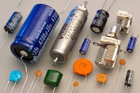
The photo below shows various types of capacitors. The green square one on the bottom is a polyester film capacitor, the round ones to the right of that one are ceramic disk capacitors, both of them use a symbol like C1 or C2 in the drawing on the right. The giant blue one and the smaller ones that have + and – written on them are electrolytic capacitors, the symbol for them is C3. They have the polarity symbols on them because you have to hook them up in the correct direction. The two with metal plates showing are variable capacitors, with the symbol shown as C4.

DIODES
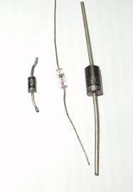
A diode is a device that allows current to easily flow in one direction, but not the other. It is like a one way valve. A diode has a cathode and an anode. If the anode is more positive than the cathode, then basically conventional current will flow from the from the anode to the cathode. I say basically because the voltage must be high enough to overcome the voltage drop of the diode. That amount varies with different types of diodes. In a silicon diode, the most common today, that voltage drop is around 0.7 volts. The picture below on the left shows 3 typical silicon diodes.

INDUCTORS
Inductors, also called chokes, temporarily store energy when a current flows thru it. Then when the current stops, they give that energy back to the circuit. If that sounds like a capacitor, it sort of is. But a capacitor does this by storing the energy electrostatically, whereas an inductor stores the energy in a magnetic field created by a coil of wire wound around a core.
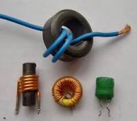
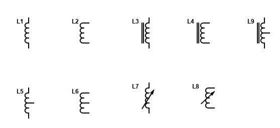
The photo above shows some different types of inductors. The symbols above show some different ways you might see an inductor in a schematic diagram. L1 and L2 are the same inductor, just with the leads drawn a different way. They are “air core” inductors (no iron). L3 and L4 are “iron core” as shown by the two additional lines. L5 and L6 are “center tapped” air core inductors. L7 and L8 are “variable” air core inductors, and finally, L9 is a center tapped iron core inductor.
INTEGRATED CIRCUITS
An Integrated circuit or IC, consists of many very small electronic circuits all on the same small wafer. They are usually made of silicon and contain many electronic components arranged to function as an entire circuit rather than using descrete components like transistors, resistors, capacitors, etc. Moderen ICs can contain millions to even billions of components.
My absolute favorite Integrated Circuit of all time is not from 2020, it’s from 1972! It’s a little 8 pin Dual-Inline-Package IC that It can be used for so many things it’s almost unbelievable. It can be used as a timer, a delay circuit, a pulse generator, an oscillator, and many more things. It’s the NE555 IC.


LEDs
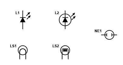
An L.E.D. or Light Emmiting Diode, is similar to a regular silicon diode. It has obvious differences in the packaging to allow the light out, but there are other differences in the way they are manufactured. First, the regular diodes use either Silicon or Germanium for the PN junction, whereas the LED uses Gallium Arsenide, Gallium Arsenide Phosphide, or Gallium Phosphide, depending on what color they are trying to produce.
The photo below shows some different colors of LEDs. They also make bi-color and even tri-color LEDs that can blend colors to make almost any color. I sure wish they made this stuff when I was a kid!

RESISTORS
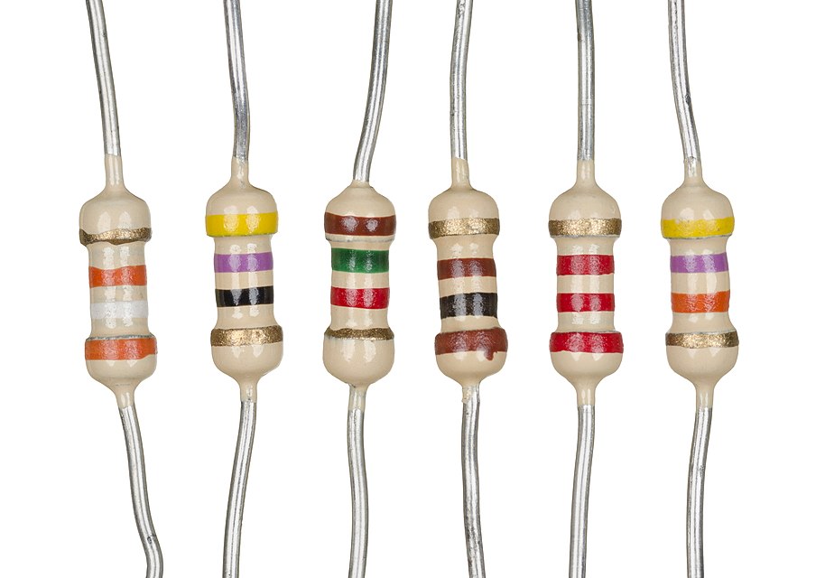
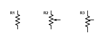
Resistors are used to resist, or reduce, the flow of current. For example, an LED without a resistor will light very brightly, just for a second, and then burn out. Resistors are also used as a voltage divider. They come in various values, measured in ohms. The higher the value, the greater resistance. They come in various physical sizes depending on how much power they can safely handle, measured in watts. They have colored bands on them to let you know what value they are. The meaning of the colors is covered in a lesson later. Here is a picture of some resistors and the schematic drawing symbol used to represent a resistor. The first symbol shows a fixed resistor, the middle one is an adjustable resistor, and the last one is a fixed “tapped” resistor.
SWITCHES
A switch is just like the switch on the wall at home to turn the lights on, only usually smaller in an electronic circuit, like the tiny little switches on a cell phone to turn the volume up and down. In this photo, there are many different kinds of switches shown. There are mercury switches that complete a circuit when the switch is tilted, rotaty switches that you turn, push button, rocker, toggle and even a microswitch.


TRANSFORMERS
A Transformer is a device that “transfers” voltage in one circuit to another circuit, and at the same time may also change the voltage to either a higher or a lower level, thus “transforming” it. It consists of two or more windings of wire, that are wound close to each other, sometimes around or inside of an iron core. Due to magnetic qualities, the current in the “primary” winding transfers current to the “secondary” winding. Depending on how many turs of wire there is in each winding, the voltage at the secondary winding can be higher, lower, or the same as the primary winding.
The schematic symbols below show, from left to right, a step up transformer, a step down transformer, a center tapped transformer, and a transformer with one primary and two secondarys.


TRANSISTORS
A “transistor” is a semiconductor device, that allows a small input signal to control a larger output signal. Because of that characteristic, a transistor is capable of acting as an amplifier. They are also used as switches. Many different types of transistors have been developed over the years. The most common types are the Bipolar Junction Transistors (BJT), and the Metal Oxide Semiconductor Field Effect Transistor (MOSFET), sometimes just called a Field Effect Transistor (FET).

