Lesson 06 – Ohms Law part 3
There is a video for this lesson
Welcome to Electronics For Fun
Lesson 6 – Ohms Law – Resistors in Series – Parallel
As I introduce new terms, I have included a link to Wikipedia. Read ahead a little, and if you still need help, you can click on any orange word below for more information than you probably want. 🙂
What is a Series – Parallel Resistor Circuit?
A Series – Parallel circuit is a combination of both. Sometimes a circuit will have a combination of both series and parallel resistors. Here is an example below.

I am going to give you two examples of a series parallel resistor circuit. First, let’s start out with the above circuit. Resistor R1 is in series with the combination of R2 and R3, which are in parallel, and that is also in series with R4. There are voltmeters across each of those branches, and also just one single ammeter. The whole thing is fed by a battery.
Sometimes it will be necessary to be able to calculate all of the values, currents, or voltage drops of a circuit like this. The best way to do that is to simplify the circuit. Let’s say that we know all of the resistor values as well as the battery voltage but we need to know the total current, shown on ammeter M4 and the voltage shown on each of the three voltmeters M1, M2, and M3.
Let’s say that R1 and R4 are 30 ohms, that R2 and R3 are 60 ohms, and that the battery is a 9 volt one. Where do we start? It varies depending on the complexity and arangement of the components. We need to know the total current before we can calculate the voltage drops. In order to calculate the total current, we need to know the total resistance. In this case, since it is a fairly simple circuit, I would look it over first and see if there was anything obvious that jumps out at me.
Look at R2 and R3; they are in parallel. Using the equations from the previous lesson, we can calculate that combination of R2 and R3 to be 30 ohms, (60 times 60) divided by (60 + 60) which is 3600 /120 = 30. Now our circuit is simply three 30 ohm resistors in series! Now it’s an easier circuit to solve for total current. Here is what that would look like below.
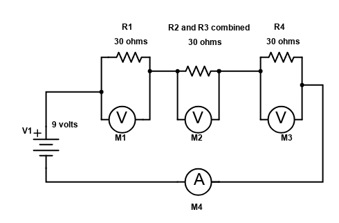
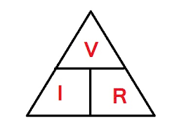
Now we figure the total resistance, simple as 30 + 30 + 30 equals 90 ohms. Next figure the total current, wait, what was that equation again? Oh yeah, we go back to our triangle which tells us that current (I) equals voltage (V) divided by resistance (R). So our total current is 9 volts / 90 ohms or .1 amp. Each of the three voltmeters would read 3 volts since all three “branches” of resistors have the same value of 30 ohms.
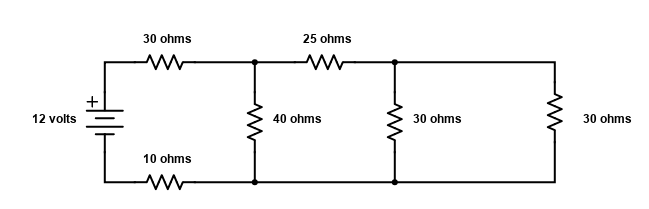
Some circuits aren’t that easy. The next one is harder if you are up to the challange. Let’s say we wanted to know the total amount of Current flowing in the circuit below. It looks like it’s complicated, right? Actually, if you know how, it isn’t really that bad. Once again I chose the values to make it easier but once you get the idea, you will be able to solve it for other values as well. Scroll down to see how!
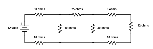
The secret is to start at the end, away from the source, in this case away from the battery. Look at the three resistors at the end, they are in series. So we are going to simplify things a bit by calculating what value those three resistors would have if they were just one resistor. Then we would redraw the diagram, sometimes in our head, sometimes on paper, depending on how complicated it was and how our memory was. So we add the three resistors up and get 8 ohms + 12 ohms + 10 ohms; 8+12+10=30 ohms. Let’s redraw the circuit below.
We added the last three resistors up and got 30 ohms. That resistor on the right hand side doesn’t really exist. It is a representation of those other three resistors that were in series in the previous diagram. It is what I call an “equivalent” resistor.
You might be able to guess the next step. This time try to imagine the last two 30 ohm resistors, which are in parallel with each other, as just one resistor. Calculating for parallel resistors, those two would be the equivalent of one 15 ohm resistor. Here is a little tip to make the math easier, if two resistors that are in parallel are the same value, the total resistance will always be half of the value. So two 30 ohm resistors in parallel would act like one 15 ohm resistor. Here is what that would look like below.
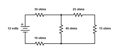
Now, for the 25 ohm and 15 ohm resistors, since they are in series, we would add the 25 ohm and 15 ohm resistors together and redraw them as one 40 ohm resistor, shown below.
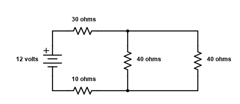
Now the two forty ohm resistors in parallel become one 20 ohm resistor.
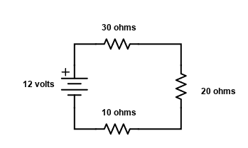
And finally, we add up the three series resistors, and the entire circuit becomes the equivalent of one single 60 ohm resistor, shown below.
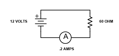
At this point we have a very simple circuit and can calculate Current = Voltage divided by Resistance, or I=12/60=.2 amps! We could even figure out all of the current thru the different branches as well as the voltage drop across each resistor if we wanted to. Where would we start on that giant task? This time we would start at the source. We already calculated the total current to be .2 amps, and we know the voltage is 12 volts. With those two pieces of information, we can calculate the rest of this circuit if we wanted to. You might want to take a little stretch break, this takes a bit of work. No one will know if if choose to skip this part except you, ha ha.

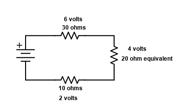
OK, if you are still with me, the circuit above is the same as one step before our final circuit before. We are going backwards now. So, we know that the current is .2 amps. From our memory, or from our triangle we know that Voltage (V) is equal to Current (I) times Resistance (R). So the 30 ohm resistor at the top would have a voltage drop of .2 amps times 30 ohms or 6 volts. The bottom 10 ohm resistor has a voltage drop of .2 amps times 10 ohms or 2 volts.
Voltage drop, what does that mean? It means that if you hooked a voltmeter across that 30 ohm resistor it would read 6 volts, and across the 10 ohm resistor it would read 2 volts. What about the 20 ohm rsistor in the drawing? Remember, that isn’t an actual resistor, it is the equivalent resistance of all of the rest of the first circuit that we started out with. In any case, it will act just like a real resistor for the purpose of our calculations. It has a calculated value of 20 ohms, and therefore would have .2 amps times 20 ohms or 4 volts across it.
So going clockwise from the battery, the 30 ohm resistor has 6 volts across it, the 20 ohm calculated equivalent resistor has 4 volts, and the 10 ohm resistor on the bottom has 2 volts across it. Notice that they add up to the 12 volts we have at the battery, 6+4+2=12 volts. That means the rest of the circuit that the 20 ohm resistor represents only has 4 volts, not 12 to start with. That circuit would look like this. The Current would be .2 amps thru both “real” resistors and also the 20 ohm “equivalent” resistor.
If we back up one more step, that 20 ohm equivalent resistor was two 40 ohm resistors, one “real” and one “equivalent”, like this diagram below.
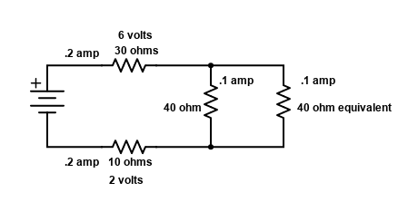
Both of those 40 ohm resistors, would divide the .2 amps, in this case evenly since both of the resistors are the same value. They would each have a current flow of .1 amp, shown above. Next, that 40 ohm equivalent resistor on the right is yet another representation of still more circuitry. The next diagram below shows how that 40 ohm equivalent resistor was representing two 30 ohm resistors with a 25 ohm resistor in series. ALMOST THERE!
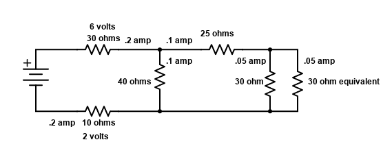
Now, that .1 amp thru the 25 ohm resistor will divide again thru both the “real” 30 ohm resistor, and the “equivalent” 30 ohm resistor. Each of those will have .05 amps flowing thru them as shown above.
Here we go again, one last time. The 30 ohm equivalent resistor on the far right of the above diagram was really three resistors. There was an 8 ohm, a 12 ohm, and a 10 ohm resistor in series, shown in the diagram below.
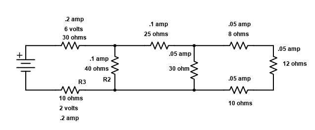
That’s it! We are back to all real resistors exactly like we started out as. The only difference is now we know more information than we knew before. The only thing left to do would be to calculate the voltage drop across each resistor. We do that by simply multiplying the Current times the Resistance.
For example, the resistor on the far right has .05 amps flowing thru a 12 ohm resistor. V=I times R, sometimes written V=I*R, or maybe V=IxR, still other times you might see just V=IR, like the triangle. Back to the far right resistor as an example, we get V=IR, so V=.05 amps X 12 ohms = .6 volts. You can do that for the rest of them if you want to. Do you want to?…. Hello?….. Is anybody there?….Hello?….. Where did everybody go?…. Oh well………
Test your knowledge if you feel like it with a little test. No cheating now!
Q1: Two 20 ohm resistors in parallel with another 20 ohm resistor in series with them would have a combined value of _____________ohms.
Q2: Three 30 ohm resistors wired in parallel, with two 15 ohm resistors in series with them would have a total value of __________ ohms.
Q3: Two 100 ohm resistors wired in parallel with a third 100 ohm resistor wired in series with them have a value of _________ ohms.

©2020 ElectronicsForFun.Com, Theme Design by Evolve Themes and Proudly Powered by WordPress