Lesson 12 – LEDs
Welcome to Electronics For Fun
Lesson 12 – Light Emitting Diodes
As I introduce new terms, I have included a link to Wikipedia. Read ahead a little, and if you still need help you can click on any orange word below for more information than you probably want. 🙂
L.E.D.s
An L.E.D. or Light Emmiting Diode, is similar to a regular silicon diode. It has obvious differences in the packaging to allow the light out, but there are other differences in the way they are manufactured. First, the regular diodes use either Silicon or Germanium for the PN junction, whereas the LED uses Gallium Arsenide, Gallium Arsenide Phosphide, or Gallium Phosphide, depending on what color they are trying to produce.
The difference in materials causes the LED to convert its energy into light instead of heat like the regular diodes. Also the voltage drop on a regular silicon diode is 0.7 volts, a regular germanium diode is 0.3 volts, and the LEDs range from 1.2 to 2.0 volts.


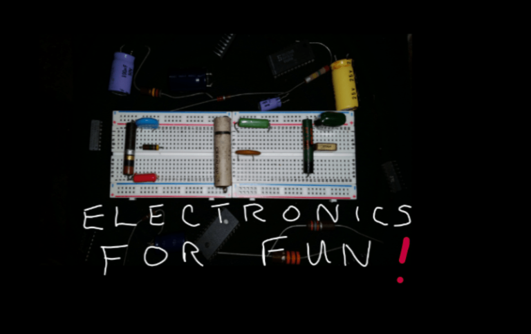
The photo above shows some different colors of LEDs. They also make bi-color and even tri-color LEDs that can blend colors to make almost any color. I sure wish they made this stuff when I was a kid!
The schematic drawing shows which way an LED is hooked up. Some LEDS have a built in resistor, but if you use the kind that don’t, and you don’t use a resistor, you just burned up a perfectly good LED! Also, please note that even though the diagram doesn’t show it, the Anode, which gets the + voltage, always has the longer lead. Hook it backwards and it won’t light.
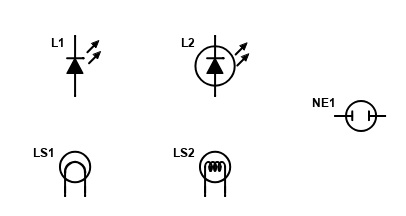
In the symbol diagram, L1 and L2 are LEDs. Of course mostly everything uses LEDs now but, just in case you see these other symbols, LS1 and LS2 are regular incandesent light bulbs, not LEDs, and NE1 shows the symbol for a Neon lamp.
Calculating The Required Resistor Value
If you are building a circuit from something you found on the Internet, it will most certainly give you the values of the components required to build it. But, suppose you want to design and build your own circuit? I’m not talking about something that requires an Engineering Degree, just something simple. Suppose for starters, you just wanted to light an LED with a battery.
Earlier in this lesson I mentioned that if you didn’t use a resistor in series with your LED, it would probably burn out quickly. So let’s figure out how to calculate the right size resistor to use. First a little more information about LEDs.
Earlier in this lesson, I said an LED had to be hooked up the right way, the longer lead, called the anode goes to plus. Well, that is what is called the forward bias, and just like a regular silicon diode, they only conduct when the voltage is applied in the forward biased direction. An LED only conducts, meaning only lights up, in the forward biased direction.
Different colored LEDS have different voltage drops. That is the amout of voltage that the LED would have across it when it was lit. The forward voltage drop of an LED is usually somewhere between 1.8 and 3.3 volts. It depends on the color of the LED. As an example, A red LED typically has a voltage drop of around 1.7 to 2.0 volts, while a blue LED is typically around 3 to 3.3 volts.
LEDs also draw different maximum amounts of current before they are ruined. A datasheet from the company where you buy your LEDs from would have that information. Fortunately, it’s not rocket science and we can get close enough easily. Let’s pretend you have a red LED that you want to light up with a 9 volt battery.
Without a data sheet handy, we know that the typical red LEDS drop 1.8 to 2.1 volts, I’m going to go with 1.8 volts. Also they normally have a maximum current rating of maybe around 20 to 25 milliamps. The more current you push thru them, the brighter they get, however, it doesn’t work like twice the current equals twice the brightness. It turns out that making an LED draw 25 milliamps is nowhere near twice as bright as it would be at 12.5 milliamps, plus your battery would not last as long. So I like to use 15 milliamps as a goal.
So let’s do a little math that we learned way back in the Ohms Law lessons. We have a 9 volt battery in series with a resistor of unknown value, and an LED that we want 1.8 volts across. Therefore the resistor has to take up the remaining voltage. We have 9 volts from the battery, minus 1.8 volts for the LED, gives us 7.2 volts the resistor should have across it.
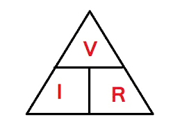

We want the current to be 15 milliamps so our triangle from before tells us that R=V/I, so if we substitute our known values we get R=7.2volts/.015amps. Dividing that out tells us we need a 480 ohm resistor. It’s good to know how to figure this out yourself, but you can also visit Digikey for an online Series Resistor Calculator. We could use a 480 ohm 1/2 watt resistor, but they only make them in 1% precision types which cost a little more, but more importantly, you would more than likely have to order it and wait for it.
Most people that experimant with electronics usually have some parts already from different projects, or they might buy a kit of assorted values. In regular 5% resistors, the closest values available are a 470 ohm and a 510 ohm resistor. The 470 ohm one would give the LED slightly more current (15.3mA), and the 510 ohm one would give it slightly less (14.1mA). Either of those would work just fine.
Test your knowledge if you feel like it with a little test. No cheating now!
Q1: The long lead is the anode and is the _____________ lead.
Q2: If an LED had a maximum current rating of 25mA, and you used a battery and a resistor that would run it at only 20mA, the LED would probably____________________________.
Q3: A Tri-color LED can __________________________.
- Only light one of the LEDs at a time.
- Blend the three LEDs brightness to make almost any color.
- Light up any one of six colors.

©2020 ElectronicsForFun.Com, Theme Design by Evolve Themes and Proudly Powered by WordPress