Lesson 03 – Your First Circuit & What is a Breadboard
The Site Menu is the ≡ in the upper right hand corner
There is a video for this lesson.
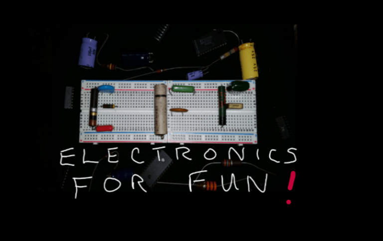
Welcome to Electronics For Fun
Lesson 3 – Your First Circuit
As I introduce new terms, I have included a link to Wikipedia. Read ahead a little, and if you still need help you can click on any orange word below for more information than you probably want. 🙂
Circuits and Schematics
Basically a circuit is one or more components hooked up to a source of electricity. In order for the circuit do actually do anything, the circuit must be complete. That means it has to have a connection from the source, thru the components, and back to the source again.
Circuit diagrams are usually shown in what is called a schematic diagram. The symbols used in a schematic are universal, meaning anyone who is familiar with them will be able to understand them anywhere in the world.
In this first diagram below, the symbol with the + sign is a battery. If you follow the wiring clockwise from there, that next symbol is an on-off switch, which is shown in the open or off position. Next is a light bulb, and finally, that goes back to the battery.

Because the switch is open, we have an incomplete, or open, circuit. Since our circuit is open, no current can flow and the lamp will not light.
This second diagram, below, is basically the same except the switch is closed, or turned on. Now we have a complete circuit, current will flow, and the lamp will light brightly.

I will be adding more schematic symbols as we cover the various components.

There is a video for this lesson that goes into more detail. Also on that video is an explanation of how a breadboard is used. Basically a breadboard is a plastic base with a bunch of holes in it used to temporarily hook a circuit up for an experiment or as a prototype testing out your circuit.
Underneath of those holes are metal contacts with spring tension on them so that they make contact with the components or jumpers that are pushed into the holes. The strips have a pattern that is very similar no matter who manufacturers the product. There is no soldering required, you just plug the components into the proper holes. Here is a picture of a typical breadboard.

I blew this photo up so you could see it better while I explain the pattern. First of all, There are two rows between the blue and red lines on each of the long sides. That is a total of 4 rows, and in each of those rows all of the pins in EACH row are hooked together, but NOT to each other.
Those rows are used to supply POWER to the board. So, with your various components in the middle, you would wire your battery or your power supply to those rows, and then use jumpers to the components in the middle. The red ones are for the + or positive side and the blue ones are for the – or negative connection.
That is for this particular board, some may be other colors like red and black, or maybe just + and -. The wide groove in the middle is for certain components that are spaced the same way such as Integrated Circuits (described in a later lesson). By the way, the spacing between each pin is one tenth of an inch.
The smaller rows of five pins on each side of the wide gap that run the other way (short side to short side) are hooked together, JUST each group of five, NOT to any of the other groups. So if you plugged a component into one of the five holes, you could make a connection with it by plugging another component or a jumper into one of the OTHER four holes in that row. If that is a little confusing, check out the video.
One thing about the video, I never really pay any attention to the numbers and letters when using a breadboard, so I kind of ignored them and filmed the video with the board upside down. It makes absolutely no difference unless you were trying to follow some directions that told you which particular hole to plug a particular component into for a project. Anyhow, Shout Out to Sean A for catching me on that.
Voltage, Current, and Resistance
The relationship between voltage, current, and resistance has been explained in many ways by many people. When I read those explanations as a kid, I have to admit, I didn’t get most of them, so I’m going to try something a little different.
Try picturing this in your mind. You have a hose hooked up outside and are going to wash the family car.

You squeeze the nozzle and water squirts out. You finish the drivers side and walk around to the passenger side and start to wet the car but the water is barely coming out. Then you notice the hose has a kink in it where it is caught under a tire.
Now try to imagine that the water itself, sitting in a tank somewhere under pressure is the voltage, the actual drops of water are the electrons, the hose is the wire, the nozzle is the on off switch, and when it is on, the flow of water is the current.
It was working pretty good until the hose got a kink in it and made it harder for the water to flow thru it because it added some resistance to the flow of water. In an electric circuit, many components have some resistance in addition to what they were designed for. Sometimes the only thing a designer of the circuit wants is resistance. A component that does that is simply called a resistor.
There is one important thing that this explanation, and also the other methods of explaining electricity that I have seen, is missing. For an electric circuit to have current flow, it must be a closed circuit. This car washing example has the water running onto the car and all over the ground. If the explanation I gave you were perfect, some of the water would seep into the ground, and some would evaporate into the sky and become rain, and be returned back into the tank where it started from. Whether you get your water from a public utility company, or a private well, that is what eventually happens.
Back to our little circuit, the diagram below is a little different that the one above where we first lit our light bulb. We have added that zigzag line on the bottom. That is the symbol for a resistor. Now the light still lights, but not as bright because the resistor reduced the amount of current. Stay with me, I will explain it more in the next lesson.

Test your knowledge if you feel like it with a little test. No cheating now!
Q1: A circuit must be complete, not open, in order to allow current to _______.
Q2: A __ in a circuit reduces the amount of current.
Q3: When we added the resistor to our circuit, the light bulb _.
Got Brighter Got Dimmer Stayed The Same

©2020 ElectronicsForFun.Com
Theme Design by Evolve Themes
Proudly Powered by WordPress