Lesson 04 – Ohms Law part 1
The Site Menu is the ≡ in the upper right hand corner
There is a video for this lesson.

Welcome to Electronics For Fun
Lesson 4 – Resistors and Ohms Law
As I introduce new terms, I have included a link to Wikipedia. Read ahead a little, and if you still need help you can click on any orange word below for more information than you probably want. 🙂
The Basics
In the last lesson, I mentioned briefly, a resistor. They add resistance to a circuit and reduce the current along with having many other uses.

For example, an LED without a resistor will light very brightly, just for a second, and then burn out. Resistors are also used as a voltage divider. They come in various values, measured in ohms. The higher the value, the greater resistance. They come in various physical sizes depending on how much power they can safely handle, measured in watts. The resistors in smaller circuits are usually only 1/2 watt or less like the ones above.
Smaller resistors have colored bands on them let you know what value they have. The meaning of the colors is covered near the end of this lesson.
There will be more details about the various resistor types and construction in Lesson 7. Ohms Law is more involved than the previous lessons and is actually split up in three lessons, Lesson 4, this one, covers resistors in series. Lesson 5 covers resistors in parallel, and Lesson 6 covers resistors in series-parallel.
Ohm’s law was named after the German physicist Georg Ohm. He was able, thru a series of experiments, to work out the properties of the relationships between voltage, current and resistance.

OK, let’s start with a very simple circuit, a battery, a resistor, and some wires. Shown above is a schematic drawing using standard symbols for a battery and a resistor. The little zig-zag line marked 100 ohms is the symbol for a resistor. To make the math easier, lets make it a 10 volt battery, and a 100 ohm resistor.
There are several simple equations that make up ohms law. The most basic one is V=IR, which means Voltage = Current times Resistance. Two things to note here, first, in older books, you might see E=IR. The E stood for EMF or electromotive force. It was changed to honor Alessandro Volta who discovered the first chemical battery to a V for Volt.
Secondly, the I which stands for Current, really should be a C in my book, but at the time the equation came out, it stood for Intensity which is what they called Current.
V=IR is used to find the voltage if you already know the current and resistance. But we can change it around to I=V/R to find current, and R=V/I to find resistance.
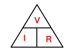
Here is a nice little triangle to help you without any algebra. Just use your finger to cover up the unknown symbol and the correct equation is what is left.
For example, we know V is 10 volts, and we know that R is 100 ohms, but we don’t know the current, I. With your finger covering the I, you can see that it can be found using V divided by R. So 10 volts divided by 100 ohms, works out to be 1/10 of an Ampere, also called amps for short.
So if you know any two of those three values, you can calculate the remaining unknown one.
Series Circuits
The circuit we just used only had one resistor. If we hook a second resistor, or more, connected end to end, they are said to be connected in series.

In the circuit above we have added a second resistor in series with the first one. Let’s say they are both 100 ohms. When resistors are in series, the total resistance is the sum of the two (or however many there are). So the total resistance is now 100 plus 100 or 200 ohms.
The current flowing thru this circuit is different than it was before because there is now more resistance. Now if we calculate I = V/R we get I = 10/ 200 or only .05 amps, half of what it was before with only one resistor.
Since both resistors are the same value, the battery voltage, 10 volts, will be divided equally across the two resistors. each resistor would have 5 volts across its terminals. Let me show you another diagram with two voltmeters, one across each resistor measuring voltage, and an ammeter used to measure the current as well.
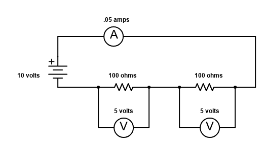
I drew this circuit with the resistors on the bottom instead of the top like the previous one to show that it makes no difference.
The electrons flow out of the battery, thru both resistors then thru the ammeter, and finally back to the battery. (Unless you follow the rules of CONVENTIONAL current flow + to – )
The ammeter up top would read .05 amps and each of the voltmeters would read 5 volts. The ammeter itself has nearly zero resistance and wouldn’t change the circuit enough to matter in most cases.
I made both resistors the same on purpose but suppose they were different. We would have to use some of those ohm’s law equations to figure the values out. I’m going to change the values to demonstrate how, but I’m still going to use values that result in numbers that are easier to calculate. That is not always the case, but this isn’t a math class, it’s an electronics class. Just know that normally, values aren’t picked to make calculations easy, they are picked to make the circuit design work.

Here is the basically the same diagram as before, but this time, let us use different values. The battery is 9 volts, the resistor on the right is 100 ohms, and the resistor on the left is 200 ohms.
First, find the total resistance. We have 100 ohms plus 200 ohms equals 300 ohms. Next find the current. Using I = V/R we have I = 9 / 300, so we have .03 amps. Next find the voltage drop across the 100 ohm resistor on the right.

Using our triangle to help us remember the equations, blocking the V shows us that the voltage across each resistor is the current times the resistance. So the 100 ohm resistor would have .03 amps times 100 ohms, giving us 3 volts. The other resistor is .03 amps times 200 ohms equaling 6 volts.
Notice that in the first series circuit, we had 5 volts across each resistor, and that added together, the 5 volts plus 5 volts equaled the 10 volts of the battery. Likewise here, in this example, the 3 volts plus the 6 volts equals the voltage of the battery, 9 volts.
So it wouldn’t matter if you had 2 resistors or 17 of them. If they were all in series, you would still be able to figure out the current and voltage. Or, if you already knew the voltage and current, you could calculate the resistance values, even if the value wasn’t some easy number I picked on purpose.
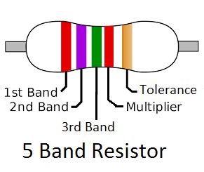
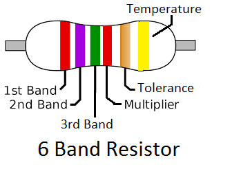
OK, so how can you tell what the value of a resistor is? Physically larger resistors, those that handle more power, usually have their value written on them. The smaller ones, up to a couple of watts, have either 4, 5, or 6 colored bands on them, like these 3 shown here, that will tell you everything you need to know.

Below is a nice chart from Wikipedia showing the 4 and 5 band resistor color codes. Note that the 4 band resistors are missing the 4th band and the Multiplier band is shifted over to the third band, and the 4th band is a space.
So using the chart below, let’s step thru the 2 resistors shown. The top one is brown, black, orange, space, gold. The colors are not that accurate on the screen, but if you follow the guide lines down to the chart, you will see what they were meant to be.
So the first band is brown, that represents the first digit, which is a one. So you would either physically or mentally write down a one. The second digit is black, that makes it a zero. So far we have 10. The third digit is the multiplier. Don’t do any math here, just add that number of zeros.
The chart shows that orange is a three, so our 10 becomes 10 plus the 3 additional zeros, making it “10” + “000”, or 10000, so it’s a 10,000 ohms or 10 Kilohms resistor.
The 4th band is gold meaning a 5% tolerance. That means the value of that resistor, according to the manufacturer, will be 10,000 ohms, + or – 500 ohms, anywhere from 9500 to 10,500 ohms. If more precision is required, you could use a 1% or a 2% resistor, but they cost a little more.

OK, now the bottom resistor with 5 bands. We have brown, black, black, red, and gold. Doing the same thing as before, except this time we get 3 digits not just 2, we get brown = 1, black = 0, black = 0 or “100”. Then we get to the multiplier which is red = 2. So now we take the “100” and add two zeros. So “100” + “00” equals “10000” or 10,000 ohms or 10 Kilohms, mostly called 10K.
Guess what, that’s exactly what the top resistor was! So why did we need an extra digit? Look at this resistor below. If it was a 4 band code, we couldn’t show 2260 ohms, we could only show 2200 or 2300.

Just one more thing, sometimes you might run into a resistor with just one black band. It is a zero ohm resistor! Wait a minute, isn’t that just a piece of wire? Why would they make a resistor with zero ohms? Well, it turns out that because in manufacturing of various devices, the components are placed on the printed circuit board by an automated process by a machine. It’s just easier with a same size resistor when they just need a jumper between the copper traces.

I know I dragged this out a little, but if you are just starting out, you really need to get this. If you already knew it, I just figured you would most likely skip past it once you refreshed your memory.
In the next lesson, we will look at resistors hooked in parallel.
Test your knowledge if you feel like it with a little test. No cheating now!
Q1: Two 20 ohm resistors wired in series have a total resistance of ______ ohms.
Q2: A 10 volt battery is connected to a 500 ohm resistor. What amount of current would flow?
Q3: A battery and a 100 ohm resistor are in series. The current is .05 amps. How many volts does the battery have?

©2020 ElectronicsForFun.Com, Theme Design by Evolve Themes and Proudly Powered by WordPress