Lesson 08 – Capacitors
Welcome to Electronics For Fun
Lesson 7 – Capacitors
As I introduce new terms, I have included a link to Wikipedia. Read ahead a little, and if you still need help, you can click on any orange word below for more information than you probably want. 🙂
What is a Capacitor?
A capacitor is a device that stores an electric charge electrostatically. Normally it has two terminals that are each wired internally to an electrical conductor, called a plate. The two plates are very close to each other and are separated by some type of insulator, called a dielectric.
When a voltage is applied to the two plates, an electric field is created. Electrons will be gathered at the plate with the more negative voltage resulting in a negative charge. The other terminal, with the more positive voltage applied, will have a lack of electrons, and therefore will have a positive charge.
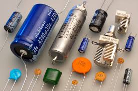
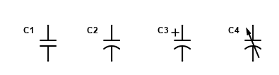
The photo below shows various types of capacitors. The green square one on the bottom is a polyester film capacitor, the round ones to the right of that one are ceramic disk capacitors, both of them use a symbol like C1 or C2 in the drawing on the right. The giant blue one and the smaller ones that have + and – written on them are electrolytic capacitors, the symbol for them is C3. They have the polarity symbols on them because you have to hook them up in the correct direction. The two with metal plates showing are variable capacitors, with the symbol shown as C4.
Capacitors come in different values, expressed in Farads. In reality, most capacitors are only a small portion of a farad, usually sold as a certain number of microfarads. They also vary in the number of volts they can safely handle. So, for example, you might see an electrolytic capacitor marked 400 microfarads at 35 volts DC.
Because a capacitor can store electrical energy (for a short period of time), it is frequently used to “filter” a DC signal, as in a power supply. If the power supply gets its energy from the wall outlet, the Alternating Current is rectified by one or more diodes but it will have some “ripple” in it, as shown by the dotted line in the diagram below.
That means that the DC output has a 60 or 120 hertz signal as part of the desired “flat” DC voltage. One or more capacitors are added to flatten that ripple out. The diagram below shows how a single capacitor can filter out a lot of the ripple. Using two stages of filtering, we can get that line pretty flat.
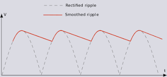
A capacitor can do that because it “charges up” during the high peaks, and then it “discharges” during the low valleys, boosting the signal up so that overall, it remains fairly constant. Without that “filtering”, there would be a “hum” in whatever the device was, like an audio amplifier for example.
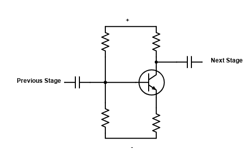
A capacitor freely allows AC to pass thru it, but blocks DC. So if we have an amplifier for example with multiple “stages” of amplification, capacitors are used to “couple” the output of one stage to the input of the next stage. It does this by blocking the DC voltages required for the amplifier to work and yet allows the AC signal, the music or whatever, to pass to the next stage.
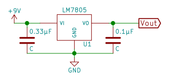
A “bypass capacitor”, also called a “decoupling capacitor” is used to bypass noise or voltage spikes on a power line feeding a circuit. Transient currents and high frequency noise, generated by other active components in a circuit, can be eliminated with a bypass capacitor. Those undesired spikes will flow through the capacitor and return to circuit ground instead of going on to the next circuit. The DC component cannot go through the capacitor and continues on to the circuit that is being decoupled.
A capacitor takes some time to charge up once a voltage is applied to it. Likewise, it takes some time to discharge when the voltage is removed. If a resistor and a capacitor are used together, we can accurately control how long those times are. Because of this, we can design circuits that will charge and discharge fast, slow or in between, according to our needs.
The RC Time Constant as it is called, is also called tau. Tau is the greek letter used to represent it in the formula τ=RC. That means that τ (the time constant in seconds) is equal to R (the resistance in ohms) times C (the capacitance in farads).
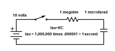
The diagram above shows a simple circuit consisting of a 1 megohm (a million ohms) resistor in series with a 1 microfarad (a millionth of a farad) capacitor. The Time Constant that we calculated, shown in the circuit diagram, i τ=RC, or 1 second. Assuming the capacitor was fully discharged to start with, and had zero volts across it, when the swich is turned on, the capacitor starts charging thru the resistor.
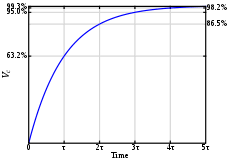
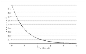
The chart on the right shows how, as time goes on, the voltage starts climbing until it reaches the battery voltage. What the chart is showing is that, for these values, during Time Constant 1, the capacitor will be charged to 63.2% of the voltage or 6.32 volts.
During Time Constant 2, it will charge to 63.2% of the remaining value, and so on until at the end of Time Constant number 5, five seconds from the time the switch was thrown, the capacitor would be 99.3% charged.
If we were discharging the capacitor with this circuit, the first Time Constant would discharge to 36.8% during the first Time Constant period, in this case 1 second, shown in the right hand graph. After the fifth Time Constant, the voltage would be very close to zero.
Capacitors in Series or Parallel
Do you remember how for resistors in series we simply added all of the resistors values up to find the total resistance? Series resistors was the easier one to solve, and the resistors in parallel was harder. For capacitors, those equations are switched! First, let’s start with capacitors in parallel, the easier one:
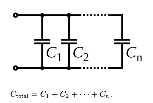
This is the easy one, capacitors in parallel. If C1 was 1 microfarad (usually written as 1µfd or sometimes 1mfd), and C2 was 2µfd, we would simply add them together. Our equation, since it is written using Farads, not microfarads, would be CT=.000001 + .000002 for a total of .000003 or 3 microfarads. You don’t even need to worry about all the zeros, just do 1 µfd + 2 µfd = 3 µfd. OK, so that was the easy one. Now with capacitors in series, that is the harder one to solve, shown below:
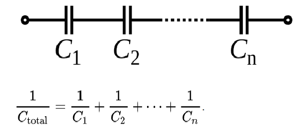
Let’s say we only had two capacitors, one was 1 µfd, and the other was 2 µfd. Rewriting the above equation while substituting the two known values would look like this: 1/CT = 1/.000001 + 1/.000002. after doing the division we would rewrite it like this: 1/CT = 1000000 + 500000, then adding them together we get 1/CT=1500000, finally we divide 1 by the 1500000 to get .0000006667. But that is the answer in Farads. so we divide by 1 million (or just move the decimal point to the right six places) giving us .667 microfarads. You can visit Digikey.com for an online capacitance calculator.
Tip, the total for capacitors in series is less that the smallest capacitor just like resistors in parallel would be. Capacitors are solved exactly the opposite way resistors are.
Capacitive Reactance
Capacitive Reactance refers to how much a capacitor resists a change of voltage across its terminals. Since a capacitor allows AC to pass freely through it but blocks DC, it’s easy to see how capacitive reactance would be dependant of what frequency was applied. The lower the frequency, the higher the reactance.
The equation for calculating capacitive reactance is XC=1/2πfC, so if we had a 1µF capacitor with 60 hertz AC, the equation would be XC=1/2 times 3.14 times 60 times .000001. Then multiplying 2 times 3.14 times 60 times .000001 gives us .0003768, which gives us XC=1/.0003768. Finally, dividing 1 by .0003768 gives us XC=2654 ohms rounded off. You can visit 66pacific.com for an online capacitive reactance calculator.
Test your knowledge if you feel like it with a little test. No cheating now!
Q1: A capacitor is made up of two plates, very close together, separated by an insulator called a ___________ .
Q2: An Electrolytic Capacitor has plus and minus markings. It must be properly connected or it _____________ .
Q3: Two 10 µfd capacitors are wired in parallel. The total value of that combination is _____________ .

©2020 ElectronicsForFun.Com, Theme Design by Evolve Themes and Proudly Powered by WordPress